How to Use MCP4725 12 Bit Digital to Analog Converter Using Arduino
2026-06-10 | By Ron Cutts
License: GNU Lesser General Public License I2C / TWI Microcontrollers PWM Arduino ESP32
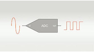
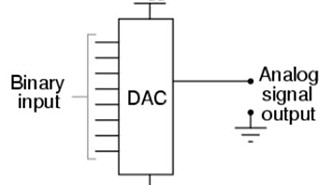
In this tutorial, we will learn how to use the MCP4725 12-bit digital-to-analog converter with Arduino and Visuino to generate square, sine, and triangle waves.
Watch the video!
What You Will Need
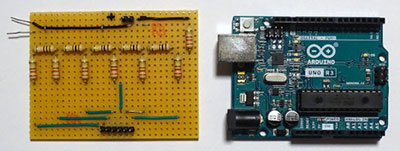
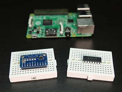
Arduino UNO or ESP32 (Or any other Board)
To do the test experiment:
Oscilloscope (Optional)
Visuino program: Download Visuino


The Circuit
Connect Arduino pin [5V] to breadboard positive pin [Red line]
Connect Arduino pin [GND] to breadboard negative pin [Black line]
Connect MCP4725 pin [Out] to 1K ohm Resistor on the breadboard
Connect other side of the Resistor to the LED pin [positive +]
Connect LED pin [negative - ] to the breadboard negative pin [Black line]
Connect MCP4725 pin [SCL] to Arduino pin [SCL]
Connect MCP4725 pin [SDA] to Arduino pin [SDA]
Connect MCP4725 pin [VCC] to breadboard positive pin [Red line]
Connect MCP4725 pin [GND] to breadboard positive pin [Black line]
Connect Oscilloscope Signal probe to MCP4725 pin [Out]
Connect Oscilloscope Ground probe to breadboard positive pin [Black line]

Start Visuino, and Select the Arduino UNO Board Type
Start Visuino as shown in the first picture. Click on the "Tools" button on the Arduino component (Picture 1) in Visuino. When the dialog appears, select "Arduino UNO" as shown in Picture 2


Generate Square Waves - in Visuino Add & Set Components
Add "Microchip I2C Digital To Analog Converter (DAC) - MCP4725" component
Add "Square Analog Generator" component
Connect "SquareAnalogGenerator1" pin [Out] to "DAC1" pin [In]
Connect "DAC1" pin I2C [Out] to the Arduino Board pin I2C [In]
Upload the Project to the board; see the "Generate, Compile, and Upload the Arduino Code" Step on how to upload the project


Generate Sine Waves - in Visuino Add & Set Components
Add "Microchip I2C Digital To Analog Converter (DAC) - MCP4725" component
Add "Sine Analog Generator" component
Set the "Frequency" in the Properties window to 0.2
Connect "SineAnalogGenerator1" pin [Out] to "DAC1" pin [In]
Connect "DAC1" pin I2C [Out] to the Arduino Board pin I2C [In]
Upload the Project to the board; see the "Generate, Compile, and Upload the Arduino Code" Step on how to upload the project


Generate Triangle Waves - in Visuino Add & Set Components
Add "Microchip I2C Digital To Analog Converter (DAC) - MCP4725" component
Add "Triangle Analog Generator" component
[Optional] Set the "Frequency" in the Properties window
Connect "TriangleAnalogGenerator1" pin [Out] to "DAC1" pin [In]
Connect "DAC1" pin I2C [Out] to the Arduino Board pin I2C [In]
Upload the Project to the board; see the "Generate, Compile, and Upload the Arduino Code" Step on how to upload the project


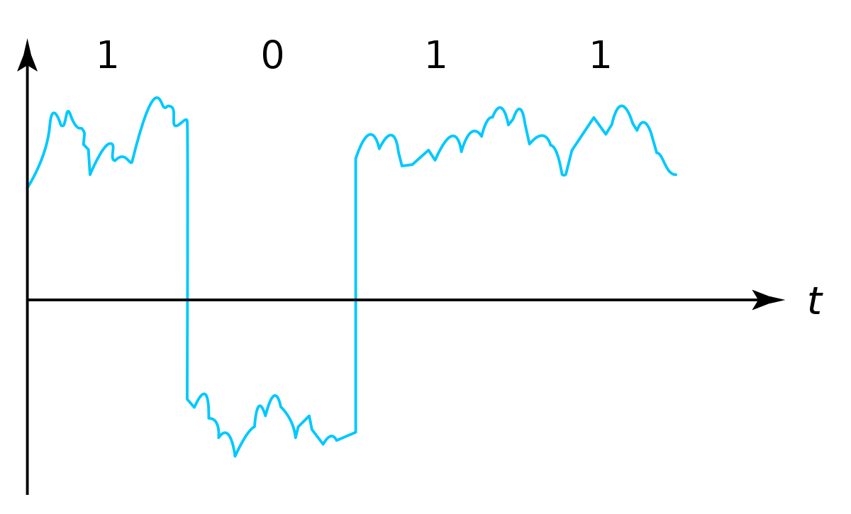
Generate Digital Pulses - in Visuino Add & Set Components
In this Example we are going to convert digital pulses from "Pulse Generator" component to an analog signal using a "Digital To Analog" component
Add "Microchip I2C Digital To Analog Converter (DAC) - MCP4725" component
Add "Pulse Generator" component
[Optional] Set the "Frequency" in the Properties window
Add "Digital To Analog" component
[Optional] Set the "True" or "False" values in the Properties window
Connect "PulseGenerator1" pin [Out] to "DigitalToAnalog1" pin [In]
Connect "DigitalToAnalog1" pin [Out] to "DAC1" pin [In]
Connect "DAC1" pin I2C [Out] to the Arduino Board pin I2C [In]
Upload the Project to the board; see the "Generate, Compile, and Upload the Arduino Code" Step on how to upload the project


Generate, Compile, and Upload the Arduino Code
In Visuino, at the bottom, click on the "Build" tab, make sure the correct port is selected, and then click on the "Compile/Build and Upload" button.

Play
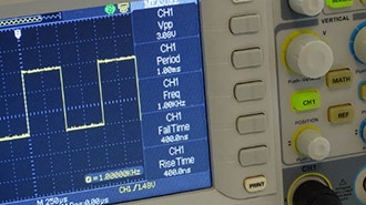
If you power the board, the LED will blink, and if you are using an oscilloscope, you should see the signal from the MCP4725 module. There are many ways to use this module; this was just a quick simple introduction to get started.
Note: In my project, I set the I2C address of the "Microchip I2C Digital To Analog Converter (DAC) - MCP4725" to 96, you should check the address of your module.
Congratulations! You have completed your project with Visuino. Also attached is the Visuino project that I created for this. You can download it here and open it in Visuino: https://www.visuino.eu