Mfr Part # 101990029
CURR SENSE XFMR 100A:0.05A 100A
Seeed Technology Co., Ltd
License: GNU Lesser General Public License Microcontrollers Test Equipment Multimeter Electricity Current Arduino ESP32 XIAO
Here in my hand is my most recent electricity bill. Every month, it is the exact same thing. I open it up and get a big old surprise at the amount written on top. I am ready to do something about this problem, but my utility bill only shows the total kilowatt-hours I used. I want to know how much of that total usage is my workshop versus charging my electric vehicle or my HVAC system. I have no idea, maybe there are some habits that I can change to reduce my bill. My name is Zach, and I am The Byte Sized Engineer. In this post, we are going to tackle this problem by building a whole-home energy-monitoring system using inexpensive components.
If we break this problem down to its core, I just need to measure the current flowing through the wires in my house. Here in North America, where I live, I have split single-phase power, which means my outlets measure 120V RMS. If I can measure and add the two currents coming into those phase wires, then multiply that sum by 120V, I get the power my house is currently using at that moment. I looked at using a dedicated current measuring IC like the ACS712, but that requires breaking the circuit to insert it in series, which is a no-go for a mains panel. A clamp meter like my Fluke 323 is better because it uses magnetic induction to measure current without breaking the wire, but I do not want to sit in front of my panel writing down measurements in a notepad all day.
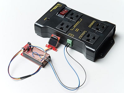
The solution is a current transformer, or CT clamp. It works like a clamp meter but connects to a microcontroller. Since a CT clamp produces current and microcontrollers read voltage, I had to add a 20-ohm burden resistor to translate the signal. With this, the current transformer will produce a small sinusoidal voltage that the microcontroller can read. That gives me a 1-volt swing when measuring 100 amps. I also had to use two 100K resistors to bias the voltage up to 1.65V so the alternating current signal does not swing below zero, which would fry the ADC on a 3.3V microcontroller. Finally, I added a 10uF capacitor to filter out any high-frequency spikes. I built this circuit on a breadboard and used a Seeed Studio XIAO ESP32-S3 to interface with Home Assistant using ESPHome.
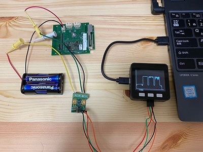
I ran into a few classic engineering hurdles during the testing phase. Measuring a space heater by clamping around the main cord, over both the hot and neutral wires, will cancel each other out, giving me a reading of zero. So, I had to split a cheap extension cord to isolate a single wire. Then, following the ESPHome documentation, I added the sensor to Home Assistant. I realized I had accidentally referenced the wrong GPIO number because the pin labeling on the board was a bit confusing. After a quick fix, I did some linear calibration in Home Assistant using my Fluke meter as a reference. I got the readings to match my Fluke meter within 0.05 amps.
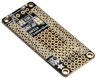
Once the prototype worked, I designed a custom PCB. I added TRS audio jacks because most off-the-shelf CT clamps use them. After ordering them from DKRed, I soldered the components on the boards and tested them. I actually got lucky, and the board worked perfectly the first time, which basically never happens. I then installed the sensors in my main electrical panel.
A quick disclaimer: working inside a mains utility panel is dangerous. If you do this, turn off the main breaker and consider hiring an electrician. Even with the main breaker off, the main lugs are still live.
My favorite part of this build is that the PCB is stackable. I started with three jacks but ended up stacking them to support nine current transformers. This allows me to monitor the two main phases and seven individual circuits. I mounted it in a 3D-printed enclosure with a laser-cut acrylic cover next to my panel.
Now that it is all integrated into the Home Assistant energy dashboard, the mystery of my electricity bill is gone. I can see exactly when the well pump kicks on, how much it costs to run the dryer, and even caught a rogue humidifier that was turning on randomly and driving up my costs. I am already using this data to create automations and save money. If you want to build your own, you can find the schematic and design files here: https://github.com/bytesizedengineering/home-energy-monitoring